HOWTO re-cap: replacing electrolytic capacitors in vintage audio equipment
Last modified: Wed Jan 3 06:38:16 2007
Disclaimer
This information is provided here on an "as-is" basis, without any guarantee. If you don't feel confident about opening up your audio equipment and using a soldering iron, then don't do it. Simply bring your vintage audio gear to an experienced technician and have him do the work for you. All told, that might be the least expensive solution.
Also please note the following only applies to solid state audio gear. Tube gear is different. See this post by markn2wae on Audiokarma for tube advice.
Recapping: replacing electrolytic capacitors
Recapping is simply that: replacing old electrolytic capacitors with new ones. So here before:
And after recapping:
Reasons for electrolytic capacitors replacement
Simply put, the reason is that eventually after some time, electrolytic capacitors go bad:
Electrolytic capacitors age, and ultimately fail. Electrolytic capacitor failure can be catastrophic (explosion, fire, smoke, short circuit and fuse blowing) or silent (electrolyte leakage, open, ESR increase, capacitance decrease).
Electrolytic capacitors aging is accelerated by heat. Very often smoothing capacitors in power supplies are the first to fail, because of the high currents flowing through them as they charge/discharge; this in turn generates heat, which cumulated with the heat from the surrounding components, accelerates aging. Decoupling electrolytic capacitors in the power supply will also suffer from the heat of the surrounding components.
ESR increase can also degrade sound quality if the electrolytic capacitor is used for coupling or in the feedback loop in preamps, where low voltages and currents are commonplace and non-linearities are more audible. In amplifiers you should also check for electrolytics in the feedback loops. Audible hum is often a sign of a failed decoupling capacitor.
Both large and small electrolytic capacitors age and fail; do not assume that a small electrolytic capacitor cannot fail.
Service life of electrolytic capacitors
To the best of my knowledge, electrolytic capacitors have an average service life of 20 to 25 years. Note the "average" in the previous phrase: some capacitors will fail in the first year of operation, some in the second, etc. And some will keep on working even after 30 years in service.
The failure rate is not constant: it follows a curve known as "bathtub curve", explained in the following graph:
The "Time" axis is not to scale:
- The "Infant Mortality" period is very short in modern electronics: 10 days to a month at most.
- The "Random failures" period corresponds to the useful service life of any component. It is usually measured in thousands of hours i.e. years.
- Finally, when components "wear-out", their failure rate increases very quickly. This last period is relatively short i.e. all components from the same batch, exposed to the same environmental conditions, will tend to fail within a few weeks/months of each other.
I guess it's safe to say that in vintage equipment from the 70's and 80's, all electrolytic capacitors have reached the end of their service life, when "wear-out" failures rates increase drastically. A re-cap job should swap out all the electrolytic capacitors, not just some. Since it's a PITA to ship or bring a piece of vintage for recapping, or just to disassemble it, one might as well just do it once every 25 years!
Basic rules of electrolytic capacitor replacement
Again, to the best of my knowledge, these are:
- Replace with same capacitance component.
- Replace with same voltage rated component or immediately next higher range. Note that higher voltage rated capacitors usually have higher ESR.
- Replace with same max. operating temperature component (usually 85C) or next higher range (usually 105C). Again note that higher operating temperature rated capacitors usually have higher ESR.
- Replace with good quality new component. Re-using a capacitor you just unsoldered from a 20 year old TV set is not going to do any good.
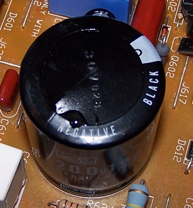
WARNING: Always check the polarity of the capacitor you are replacing. Electrolytic capacitors have + and - leads, with the negative lead usually clearly labeled. NEVER REVERSE these leads. Capacitors will instantly be destroyed if their polarity is reversed, possibly taking out a few more components with them. You have been warned!
Note: when the negative lead is not clearly labeled, it is the shorter lead.
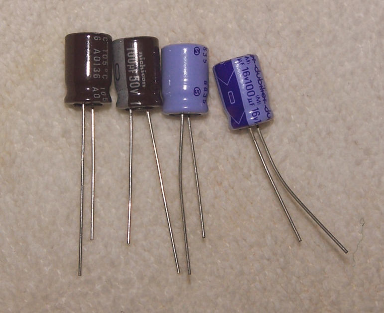
The picture below shows some clearly labeled capacitors. The blue ones are from Dubilier, the brown ones are Nichicon.
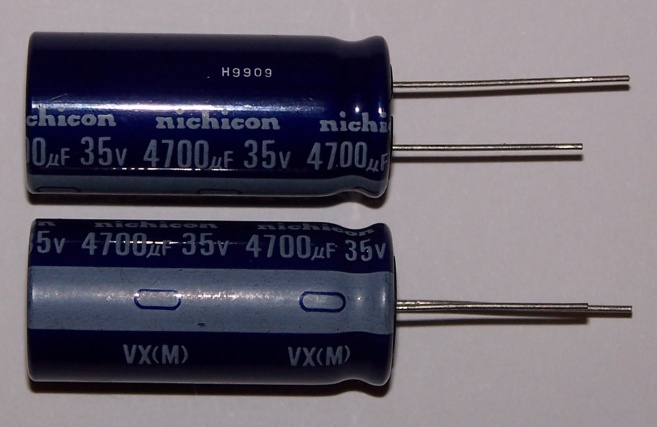
Here is a pair of medium-size Nichicon 4700uF/35V 85C electrolytic capacitors for power supply usage. The negative lead is clearly labeled with a white strip and a negative sign, and is shorter.
Here is another view of the same Nichicon capacitors. We can see a code 9909 which may indicate the year and month of manufacturing (September 1999), and another code VX(M) that indicates the series and tolerance rating of this capacitor. If we look up the Nichicon website we can find more information about these VX-series capacitors.
Reading capacitor values and specifications
Sometimes reading capacitor values from schematics or as found on the body of a capacitor is not easy. Here are a few tips for interpreting these values correctly.
- Capacitance values for electrolytics found in audio units are always stated in uF e.g. 0.5uF, 3.3uF, 10uF, 330uF, 4700uF, 15000uF, etc. Note the letter before the capital F is a micron sign, not really a lower-case u. The Farad is a very large unit of capacitance, so for electrolytics the value is stated as microFarads, or uF.
- Capacitors are rated for a maximum operating voltage and this should not be exceeded. Common values are 6.3V, 10V, 16V, 25V, 35V, 40V, 50V, 63V and so on.
- Maximum operating temperatures are always specified in degrees Centigrade (C). Two common values I know of are 85C and 105C, and I have seen 125C-rated capacitors for special applications, but these are rare.
Occasionally, capacitors are specified for a special application i.e. low ESR for high-frequency switching power supplies, etc. Of special note are non-polarized electrolytic capacitors, these are clearly labeled NP, and usually require an exact replacement.
Tools and basic skills
If you have good soldering skills and the right tools, capacitor replacement is really not that difficult. But good soldering skills don't come naturally, so don't undertake a major re-cap if you don't have enough experience.
Here are the tools I use for the occasional re-cap job:
Nothing special really. The alcohol and q-tips are for cleaning the solder resin after soldering in the new caps. The soldering iron is a 30W model. The solder pump is of the cheap kind but gets the job done. For regular re-cap jobs a proper solder pump is required.
Two optional items you may want to use:
(thanks to Audiokarma member archie2 for suggesting the following optional items)
- A soldering gun (the instant heating up makes it easier to use and safer), but make sure you have a small enough tip. Also note that soldering guns are not recommended for work near integrated circuits or FETs.
- Solder with some silver content: this improves electrical transfer.
Recommended re-cap procedure
Begin with listing all the capacitors you intend to replace. This is made much simpler by having a copy of the schematics of the audio gear on which you are working.
If you don't have the schematics, open your equipment and carefully check and write down the ratings (capacitance, voltage and max. operating temperature if 105C) of all the electrolytic capacitors used, and their polarity. It doesn't hurt to check the schematics against the actual values, too.
Recapping is tedious hard work. I don't recommend replacing more than half a dozen capacitors in a single session. Needless to say, completely unplug the amplifier from the mains line before you start any re-cap work on it.
Warning: The large electrolytic capacitors in the power supply can store a considerable amount of energy. Make sure they are discharged, or use a small "bleeder" resistor (220 ohms) to discharge them before you begin any sort of maintenance work.
The following steps are for each electrolytic capacitor replaced:
- This may seem strange, but I usually start with re-melting and adding a tiny bit of solder to the solder pads of the capacitor that I want to replace.
- Heat up the leads of the capacitor to be replaced and gently pull it out once the solder has melted on both leads. If there is too much solder to start with, remove it beforehand with the solder pump.
- Remove any remaining solder with the solder pump.
- Insert the new capacitor, making double-sure it is correctly oriented. Remember that the capacitor marking indicates the negative (shorter) lead, whereas the PCB silkscreen indicates the positive (e.g. CS12 on the picture above). Bend the leads out slightly so the capacitor won't fall out once you apply the solder.
- Apply the solder and let it melt over each lead and solder pad for a couple of seconds. Let the capacitor cool down for a few seconds between each lead.
- Cut the leads and clean the solder pads off any resin residue with the q-tips and alcohol. This step can be done last after replacing all the capacitors for this session.
I also keep all the old capacitors I have replaced in a small plastic box until the entire recapping job is finished. I sometimes check the values of a few old capacitors with a capacitance meter; very often I find that they are at the low end of the +/- 20% tolerance, or below.
All in all an entire session for half a dozen capacitors will last anywhere from 15 to 30 minutes. What I usually do is try out the amplifier after each re-cap session; like that I can easily back-track in case there is a problem.
It can be extremely frustrating to change 30 capacitors in a two hours session, only to find out that the amp/receiver on which you are working doesn't play any sound anymore, whereas it was "working fine" before you began the re-cap session...
More pictures coming!
Ultimate disposal of electrolytic capacitors
(thanks to Audiokarma member rulerboyz for suggesting this paragraph)
Unfortunately we are facing the problem of chemical pollution from our landfills. How do we dispose of electrolytic capacitors in an ecologically-acceptable way?
I found the following information on the Nichicon US website:
The following slightly more informative guidelines come from the US Nippon Chemi-Con website:
From the above warnings and guidelines, it would seem that aluminium electrolytic capacitors are not particularly toxic, whether incinerated or buried.
Links
A few websites which I have found informative: